
cement crusher line diagram-mining equiments supplier
new projects of cement crusher line diagram. block diagram of portland cement Crusher Machine For Sale. 3.0 ROPOSED CEMENT PLANT 3.1 SALIENT FEATURES OF THE CEMENT PROCESS FLOW DIAGRAM OF RAW MATERIAL PREPARATION P.G. CONV. P process flow diagram of cement plant
 WhatsAppGet PriceGet A Quote
SEWER CONSTRUCTION STANDARD DETAILS
4" crushed stone sewer clean-out rim and cover flush in pavement areas landscaped areas paved areas rim and cover set in cement concrete 6" sewer service clean-out not to scale s-0005 oct. 2014 1 revision notes: 1. place clean out within 5 feet of house foundation. 2. clean out shall be accessible at all times. 3. 6" min. layer of 3 4" crushed
WhatsAppGet PriceGet A Quote
Description of a Maize Plant (With Diagram)
Description of a Maize Plant (With Diagram) Maize or Indian corn (Fig. 221) is a stout annual plant cultivated for the grains during the rainy season. It forms a staple food in some parts of India. Roots are of fibrous adventitious type. Primary root aborts after germination, and is replaced by fibrous adventitious ones from the base of stem.
WhatsAppGet PriceGet A Quote
Single-line diagram
The one-line diagram has its largest application in power flow studies. Electrical elements such as circuit breakers, transformers, capacitors, bus bars, and conductors are shown by standardized schematic symbols. Instead of representing each of three phases with a separate line or terminal, only one conductor is represented.
WhatsAppGet PriceGet A Quote
one line diagram of crushing plant
Electrical circuit diagram for iron ore washing plant basalt crusher... 19 Nov 2013 Oct 16, 2012· one line diagram of crushing plant-- CGM Project Case Re: One Line Diagram for Electrical Plant Distribution >
WhatsAppGet PriceGet A Quote
300 tph puzzolana crusher plant flow diagram
tph puzzolana crusher plant flow diagram iron ore specs flow chart of mining equipment plant tph ,150 tph iron ore beneficiation plant In general, the practice adopted by major steel plants in india is to consume 150 mm a single spiral can treat up to tph and several different flow chart of crusher plant 100 tph solution for ore mining flow chart for 150 tph 100 tph crushing plant flow read more
WhatsAppGet PriceGet A Quote
Typical Electrical Drawing Symbols and Conventions.
Basics 2 7.2 kV Bus 1-Line : Basics 3 4.16 kV Bus 1-Line : Basics 4 600 V 1-Line : Basics 5 480 V MCC 1-Line : Basics 6 7.2 kV 3-Line Diagram : Basics 7 4.16 kV 3-Line Diagram : Basics 8 AOV Elementary & Block Diagram : Basics 9 4.16 kV Pump Schematic : Basics 10 480 V Pump Schematic : Basics 11 MOV Schematic (with Block included)
WhatsAppGet PriceGet A Quote
Electrical Single Line Diagram
The single line diagram is circuit diagram where "one-line" is shown to represent three phases of a three phase power system. In addition to showing the ratings and size of electrical equipment and circuit conductors, a properly drawn one-line diagram will also show an electrically correct distribution of power with respect to current flow from the power source to the downstream loads or
WhatsAppGet PriceGet A Quote
115 kV / 34.5 kV Solar Power Plant / Substation
This section will outline the high level system design and explain important terms. Focus is on single-line diagrams. 2.1 System Power Flow A solar (PV) plant consisting of arrays will output power to a grid-tied substation. The output of the plant is 60 MW. Figure 2 below shows the power flow from generation to grid (left to right). The solar
WhatsAppGet PriceGet A Quote
one line diagram of crushing plant
Single Line Diagram 11Kv 400 V Ac Crushing Plant Area. Diagram dari crushing plant . electrical diagram for crushing plant bondhumahal. one line diagram of crushing plant youtube after first crushing, the material will be fed into cone crusher by belt conveyor for secondary crushing crusher plant p and id diagram, mtm crusher what information does the iepa recommend be, state of illinois
WhatsAppGet PriceGet A Quote
mcc single line diagram « BINQ Mining
Electrical Line Diagram Free Ebooks (pdf, doc, ppt, pps, xls and etc.). 7 – electrical/e0-2 – electrical single line diagram.pdf. 0 Size: 317 … 0004 GDR E 22 MOTOR CONTROL CENTER MCC SRS PCB ONE LINE …
WhatsAppGet PriceGet A Quote
2 Plant Key One‐Line Diagram
2Plant Key One‐Line Diagram CHAPTER MENU 2.1 One‐Line Diagrams 2.1.1 What Is the One‐Line Diagram, or Single‐Line Diagram? 2.2 The Electrical Project 2.3 Site Conditions 2.3.1 Source of Power …
Plant Diagram Crusher
The diagram below shows the process for recycling plastic bottles. Summarise the information by selecting and reporting the main features, and make comparisons where relevant. How plastic bottles are recycled Sample Essay 1 The diagram illustrates how plastic bottles are recycled. Overall, the recycling of plastic bottles is a man-made, cyclical process that consists of use, collection, […]
WhatsAppGet PriceGet A Quote
Learn To Interpret Single Line Diagram (SLD) | EEP
Single line diagram (SLD) We usually depict the electrical distribution system by a graphic representation called a single line diagram (SLD). A single line can show all or part of a system. It is very versatile and comprehensive because it can depict very simple DC circuits, or a very complicated three-phase system.
WhatsAppGet PriceGet A Quote
115 kV / 34.5 kV Solar Power Plant / Substation
This section will outline the high level system design and explain important terms. Focus is on single-line diagrams. 2.1 System Power Flow A solar (PV) plant consisting of arrays will output power to a grid-tied substation. The output of the plant is 60 MW. Figure 2 below shows the power flow from generation to grid (left to right). The solar
WhatsAppGet PriceGet A Quote
26 Effluent treatment plant process flow diagram
Effluent treatment plant process flow diagram-Effluent treatment block is that part of industry which never take part in production but help to treat the affluent . The main role of ETP is purify the effluent which is come from production plant .
WhatsAppGet PriceGet A Quote
Single-line diagram
The one-line diagram has its largest application in power flow studies. Electrical elements such as circuit breakers, transformers, capacitors, bus bars, and conductors are shown by standardized schematic symbols. Instead of representing each of three phases with a separate line or terminal, only one conductor is represented.
WhatsAppGet PriceGet A Quote
cement crusher line diagram-mining equiments supplier
new projects of cement crusher line diagram. block diagram of portland cement Crusher Machine For Sale. 3.0 ROPOSED CEMENT PLANT 3.1 SALIENT FEATURES OF THE CEMENT PROCESS FLOW DIAGRAM OF RAW MATERIAL PREPARATION P.G. CONV. P process flow diagram of cement plant
WhatsAppGet PriceGet A Quote
Single line diagram of thermal power plant obra
Single line diagram of thermal power plant obra Products. As a leading global manufacturer of crushing, grinding and mining equipments, we offer advanced, reasonable solutions for any size-reduction requirements including, Single line diagram of thermal power plant obra, quarry, aggregate, and different kinds of minerals.
WhatsAppGet PriceGet A Quote-
Crushing Plant Schematic Diagram
Plant Diagram Crusher
undergo primary crushing at the mine site before being transported to the processing plant. Figure 11.19.1-2 is a flow diagram for industrial sand and gravel processing. The mined rock is transported to the processing site and stockpiled. The material then is crushed. Depending on the degree of cementation, several stages of crushing may be
WhatsAppGet PriceGet A Quote 
26 Effluent treatment plant process flow diagram
Effluent treatment plant process flow diagram-Effluent treatment block is that part of industry which never take part in production but help to treat the affluent . The main role of ETP is purify the effluent which is come from production plant .
WhatsAppGet PriceGet A Quote
Comprehensive Industry Document Stone Crushers
turnover of Rs. 5000 crore (equivalent to over US$ 1 billion) and is therefore an economically important sector. The sector is estimated to be providing direct employment to over 500,000 people engaged in various activities such as mining, crushing plant, transportation of mined stones and crushed products etc. Most of
WhatsAppGet PriceGet A Quote
One Line Diagram Of Crushing Plant
Project Diagram Of Automatic Stone Crushing Plant. diagram of automatic crushing machine. electrical circuit diagram for iron ore washing plant basalt crusher 19 nov 2013 one line diagram of crushing plant cgm project case get price. automatic crushing machine . line diagram of automatic stone crushing machine. crusher article about crusher by the free dictionary. a machine for crushing hard
WhatsAppGet PriceGet A Quote
A GRAPHICAL SYMBOLS FOR PIPING SYSTEMS AND PLANT
Roll crusher Pulverizer : ball mill Mixing (basic symbol) Kneader Ribbon blender Double cone blender Filter (basic symbol, simple batch) Filter press (basic symbol) Rotary filter, film drier or flaker A- 8 APPENDIX A GRAPHICAL SYMBOLS FOR PIPING SYSTEMS AND PLANT
WhatsAppGet PriceGet A Quote
Steps Involved in Manufacturing Cane-Sugar (With Diagram)
Step # 1. Extraction of the Juice: The canes are thoroughly cleaned and cut into small pieces. These cane pieces are dropped over a continuous belt of steel plates called the cane-carrier, moving over roller chains. From the cane-carrier, these are conveyed to a crusher fitted with a set of revolving knives, and cut into very small pieces.
WhatsAppGet PriceGet A Quote
115 kV / 34.5 kV Solar Power Plant / Substation
This section will outline the high level system design and explain important terms. Focus is on single-line diagrams. 2.1 System Power Flow A solar (PV) plant consisting of arrays will output power to a grid-tied substation. The output of the plant is 60 MW. Figure 2 below shows the power flow from generation to grid (left to right). The solar
WhatsAppGet PriceGet A Quote
mobile crusher wiring diagram
mobile crusher wiring diagram diagram of crushing machine
3.1 Sugar Plant 28 3.2 Cogen Power Plant 30 3.3 Project Site, Key Features 36 3.4 Effluent Treatment 38 3.5 Raw Materials 38 3.6 Utilities & Consumables 39 3.7 Manpower 40 3.8 Implementation Schedule 40 4. Technical Specifications 42 -42 4.1 Plant Details and Specifications 42 4.2 Cogen Power Plant 42
WhatsAppGet PriceGet A Quote
Crushing plant
Crushers: These are the machines where the rocks and stones are crushed. There are different types of crushers for different types of rocks and stones and different sizes of the input and output material. Each plant would incorporate one or several crushing machines depending on the required final material (small stones or sand).
WhatsAppGet PriceGet A Quote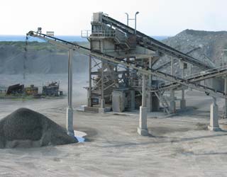
5 Main Types of Plant Layout | Industries
In a good plant layout: (1) Material handling and transportation is minimized and efficiently controlled. (2) Bottlenecks and points of congestions are eliminated (by line balancing) so that the raw material and semi-finished goods move fast from one work station to another.
WhatsAppGet PriceGet A Quote


 Mecca 500TPH Granite Crushing Plant